Conner Miles
Forging the future through engineering ingenuity.

About Me
I graduated cum laude from the University of Florida with a degree in aerospace engineering and now work as a Quality Engineer at Collins Aerospace. I'm driven by a deep curiosity and a desire to shape the future of aerospace technology through hands-on problem-solving, continuous learning, and cross-disciplinary collaboration.My passion for engineering began in elementary school, inspired by my grandfather’s work on the Mercury and Gemini space missions. His legacy continues to motivate me as I pursue opportunities to contribute meaningfully to the industry and uphold a spirit of innovation.Outside of work, I enjoy exploring complex systems—whether through strategy games like Catan, my growing collection of model trains, or building autonomous vehicles for a custom O-gauge layout. I’m also a lifelong musician: I play piano, guitar, and French horn proficiently, and have experimented with instruments like the trombone, violin, trumpet, and accordion. Creativity and precision fuel everything I do, both in and out of the workplace.
Experience
As part of the Gatorloop Design Team, I contributed to the development and refinement of mechanical stability components for our team's hyperloop pod. Collaborating with team members, I played a crucial role in setting and maintaining deadlines for manufacturing, testing, and reporting on mechanical systems. Utilizing my expertise in SolidWorks and finite element analysis, I designed parts that were optimized for performance while adhering to budget and timeline constraints. Moreover, I contributed during virtual and in-person meetings, by ensuring effective communication and collaboration among team members. My experience with Gatorloop not only sharpened my technical skills but also instilled in me a deep appreciation for teamwork and innovation in the pursuit of cutting-edge aerospace technology.

During my tenure at the Hilton Garden Inn, I served as a Night Auditor, where I operated independently to oversee hotel operations during overnight shifts. In this role, I demonstrated strong organizational skills and attention to detail while ensuring guest satisfaction and performing nightly accounting duties. Moreover, I exhibited flexibility and a willingness to support the team by eagerly picking up shifts when available. Additionally, I took the initiative to streamline the night audit process by developing a VBA code, significantly enhancing efficiency and accuracy. My dedication and proactive approach were recognized through commendations as 'employee of the month,' underscoring my commitment to excellence in every aspect of my work.
Personal Projects
"Engineering isn't about perfect solutions; it's about doing the best you can with limited resources and time." - Scotty, Star Trek
In my extracurricular pursuits, I engage in a diverse array of personal projects that underscore my commitment to innovation and craftsmanship. Chief among these endeavors is my exploration of additive manufacturing, wherein I navigate the complexities of 3D printing to create a variety of tools and parts. From engineering custom components for personal devices to prototyping future innovations, I am impressed by the transformative potential of this technology.Furthermore, I have recently delved into the realm of laser engraving, utilizing precision optics to add intricate designs to a number of objects. This fusion of technology and artistry allows me to experiment with complex patterns and textures, elevating plain surfaces into bespoke works of art.These personal pursuits serve as a testament to my enduring curiosity and unwavering dedication to pushing the boundaries of creativity and innovation. Whether through additive manufacturing, laser engraving, soldering, or other artisanal endeavors, I find great fulfillment from the process of bringing ideas to fruition in tangible and impactful ways.
Display Shelves
3D Models
Hotel Models
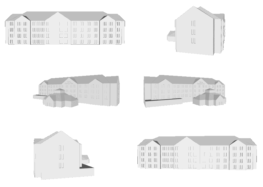
As a gift to the manager at the Hilton Garden Inn, I rendered a 3D model of the hotel using SolidWorks and then 3D-printed it for him. The following year, I did the same thing with the Homewood Suites after he was promoted to dual-manager of both hotels.I was able to use Google Earth to get a working outline of each building, but then took pictures of the outside of the buildings and used ImageJ to extrapolate the size of windows and distances between them. Much of the roofing was guess work, as it was not easy to determine the exact slopes of the different sides of the roof. I spent a lot of time making the logo on the front of the Homewood Suites (specifically the duck), not really thinking about how small it would end up being on the physical model. After printing out the model, the duck is hardly visible, although this could have to do with my layer settings, which I had set fairly high to reduce print time.



Arduino Sings Happy Birthday
For the final project in my elements of electrical engineering course, I was given free-range over what I wanted to do, as long as it utilized at least three components with the Arduino. As a music lover, I wanted to create some sort of musical instrument, using the Arduino. I was considering creating a miniature version of a Theremin, but opted in a crunch for time, I had to lower my ambitions slightly.Instead, I wrote a serious of subroutines that would play the twelve notes of the chromatic scale. I had to convert the pitches into frequencies and then used the piezo of the Arduino to play the notes. My roommate's birthday was coming up, so I decided there was no better song that 'Happy Birthday' for this project.I also decided to implement the LCD display to show the phrase "Happy Birthday!" as it played the song. Along with this, I included a potentiometer that could be used to brighten or dim the display.
Material Analysis through Vibrational Frequencies
Group Report with: Trevor Evetts, Donald Luchetti, & Mayur Patel
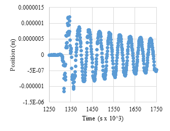
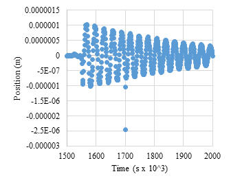
The experiment conducted aimed to analyze the vibrational frequencies of two materials, 6061-aluminum and carbon fiber, using Bernoulli-Euler Beam Theory. The frequencies were obtained through strain gauge and accelerometer measurements, allowing for comparisons of properties such as Elastic Modulus and dampened natural frequency. Results indicated that carbon fiber displayed higher stiffness and frequency compared to 6061-aluminum. Carbon fiber's average frequency was 32.88 Hz, with an elastic modulus of 63.0821 GPa, while 6061-aluminum had an average frequency of 20.87 Hz and an elastic modulus of 52.6840 GPa. Damped natural frequencies showed minimal differences between the materials, suggesting negligible effects from nonconservative forces like friction or air resistance.
Testing Setup
Wiring Diagram
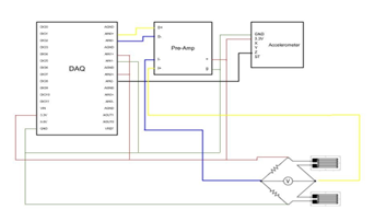
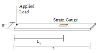
The experiment's setup involved conducting oscillation tests on cantilever beams of both materials, measuring their periods and frequencies. Carbon fiber exhibited shorter periods and higher frequencies, indicating its greater rigidity and resistance to bending compared to 6061-aluminum. Analysis of the damped natural frequency revealed minimal differences between the materials, suggesting that nonconservative forces had little effect on their oscillations. Additionally, strain analysis showed that carbon fiber experienced lower strain under similar loads, further highlighting its superior mechanical properties. Accelerometer data depicted similar trends in oscillation behavior for both materials, with decreasing amplitudes over time due to damping effects. Overall, the experiment provided valuable insights into how material properties influence vibrational behavior, with carbon fiber demonstrating greater stiffness and frequency compared to aluminum.
Carbon Fiber Position vs Time
Aluminum Position vs Time
Aileron Deflection Wind Tunnel Experiment
Group Report with: Sophia Hernandez-Davila & Mayur Patel
For my final project in the aerospace sciences lab, I modified a 3D model of a NACA 2412 airfoil by integrating custom-made ailerons at various deflection angles. Mounted in a wind tunnel using a specialized bracket, we aimed to quantify the effects of aileron deflection angles on lift and drag forces.In the pursuit of enhanced aircraft maneuverability and efficiency, control surfaces like flaps and ailerons have proven indispensable. Flaps, synchronized on both wings, optimize lift and reduce stalling speed during critical phases such as takeoff and landing. Conversely, ailerons, positioned at wingtips, facilitate precise roll control by deflecting in opposite directions.
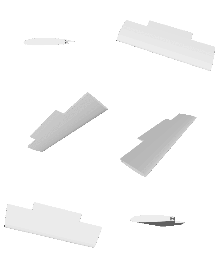

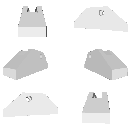
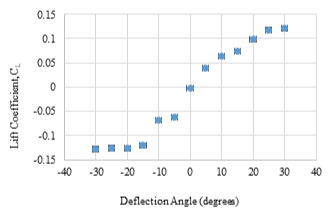
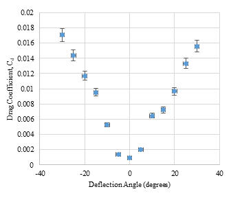
Our experiment focused on analyzing the impact of ailerons on a NACA 2412 airfoil. By subjecting a modified airfoil to wind tunnel testing, we aimed to discern the aerodynamic effects of insertable ailerons across a range of deflection angles (-30° to +30°). Through correlating voltage readings with force measurements, we determined lift and drag coefficients plotted against aileron deflection angles, revealing significant trends. Despite minor discrepancies attributed to factors like aerodynamic asymmetry and measurement errors, the experiment elucidates the fundamental relationship between aileron deflection and airfoil performance.
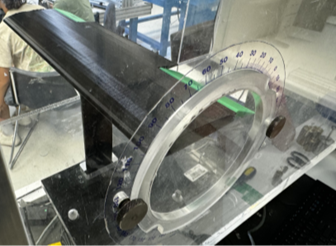
The experiment's findings, aligned with established aerodynamic principles, underscore the critical role of control surfaces in aircraft design. While limitations exist, such as unanalyzed variables and idealized experimental conditions, the study contributes valuable insights to the ongoing quest for safer, more efficient aerospace solutions. Future research endeavors could explore additional factors and real-world applications to further refine our understanding and optimize aircraft performance.
Mitigating Regolith Accumulation
Group Report with: Jorge Arredondo, Eliott Blanchard, Trevor Evetts, Jeisson Hernandez, Chris Horsa, Mayur Patel, & Tulsi Patel
As we set our sights on further exploration of celestial bodies, such as the Moon, mitigating lunar regolith accumulation on lunar landing craft becomes paramount. Lunar regolith, the layer of loose, fragmented material covering the lunar surface, poses significant challenges to spacecraft and equipment due to its abrasive nature and propensity to adhere to surfaces. Developing effective methods to prevent regolith buildup is crucial for maintaining the functionality and longevity of lunar landing craft. This project was a group effort and focuses on addressing this challenge by devising innovative techniques to mitigate regolith accumulation, ensuring the success of future lunar missions.

Our team was called the 'Mitigators' and we spent a full semester drafting and analyzing our solution for the lunar regolith problem.
Solution Overview
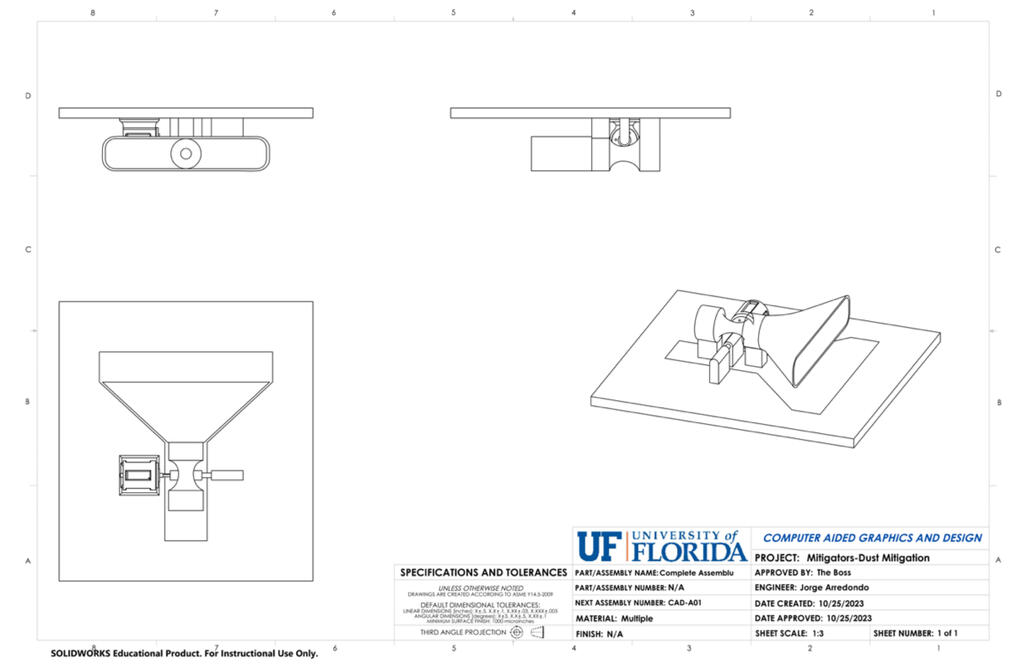
Our solution is comprised of a network of interconnected nozzles designed to create a barrier against lunar regolith accumulation. The nozzles utilize a convergent-divergent design to accelerate fluid to supersonic speeds. Attached to a rotating plate, these nozzles can be sealed when not in use. The rotational mechanism includes a female hinge welded inside the HLS and a male hinge affixed to the hatch door, enabling seamless movement. A stepper motor housed in an enclosure mount controls the rotation. Computational Fluid Dynamics (CFD) simulations determined the optimal number of nozzles needed. Structural and material analyses guided the selection of TZM Alloy for the nozzles and Aluminum 7075-T6 for the body, hinges, motor mount, and motor. Attachment methods involved bolts for motor mount flexibility and welding for robustness. Dual fastening strategies ensure both adjustability and durability. These meticulous design considerations aim to mitigate lunar regolith accumulation effectively while maintaining structural integrity and operational efficiency.

Power System Analysis
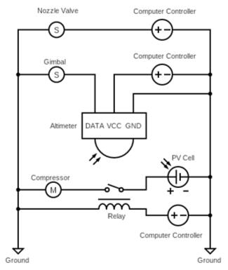
The Power System Analysis indicates that the valves and actuators controlling the liquid nitrogen flow during descent are manageable within the spacecraft's power system, typically capped at 2.5 kW. The estimated power needs of the dust mitigation system, outlined in Table VI, include valves, actuators, on-board computers, and potentially a compressor. Linear actuators are projected to consume around 120 W, well within spacecraft power limits. Options for managing nitrogen pressure, like a compressor, require additional power but may be supplemented by solar panels, with estimates suggesting up to 13 kW of additional power from on-board panels. Circuit schematics (shown below) let us detail electrical connections for the dust mitigation system, ensuring efficient power distribution. Additionally, preexisting systems aboard the Starship HLS, such as photovoltaic cells and fuel cells, contribute to power generation and were included in our analysis. Solar panel calculations estimate HLS power output, while load power profiles consider system energy consumption, enabling accurate power management and duty ratio calculations.
Thermal Analysis
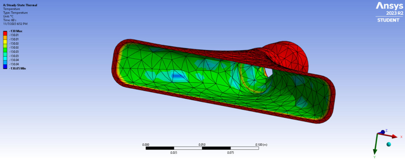
Thermal analysis underscores the paramount importance of managing heat loads and environmental temperatures, particularly during lunar landing, to ensure the efficacy and reliability of the dust mitigation system and overall Starship HLS functionality. Verification of the thermal control system's design involves comprehensive assessments of factors like cost, mass, volume, and power requirements, aligned with mission-specific needs. Ansys simulations provide insights into temperature maps and heat flux affecting the nozzle, confirming the suitability of material selection and design choices. Thorough testing and verification, along with quantitative assessments of thermal loads, ensure the chosen thermal control system's effectiveness and efficiency in maintaining required temperature ranges. The section also explores options for thermal insulation, considering materials like AISI 304 steel, known for its cryogenic properties, and addressing mounting challenges within the spacecraft fuselage.I had never used Ansys prior to this course, so it was a particular challenge for me, since I was put in charge of the thermal analysis. A few YouTube tutorials gave me enough understanding of the software to generate the temperature map pictured below. This visual representation illustrates the temperature distribution across the nozzle, using colors to denote varying temperature levels and proved vital for the analysis of heat distribution and thermal behavior in the cold vacuum of space.
Conclusion
In conclusion, our design for a liquid nitrogen-based dust mitigation system presents a comprehensive solution to safeguard the Starship HLS during lunar landings. With 50 strategically positioned nozzles, crafted from suitable alloys and supported by sturdy mechanisms, our system effectively creates a protective barrier between critical spacecraft components and lunar surface dust. The detailed component list, accounting for costs and weights, ensures a thorough understanding of the system's physical requirements. The chosen materials and components are well-suited for space applications, promising reliability and functionality. Furthermore, the incorporation of essential elements like bolts, friction stir welding, LN2 tank, and reinforced rubber pipes enhances the system's performance and integration. Despite the challenges posed by limited public information on the HLS, our design offers a robust solution to mitigate lunar plume effects during both ascent and descent phases, setting a solid foundation for successful lunar missions.
Static Truss System
This project was done for my statics course and involved the development of a program for truss analysis, focusing on both planar and spatial (3D) trusses. Initially, the task required understanding the theory behind truss analysis and modifying a provided planar truss template program to analyze spatial trusses. The project involved extensive inputting of nodal coordinates, member connectivity, support reactions, and external loads. Additionally, computations for unit vectors, coefficient matrices, and load vectors were essential for truss analysis. The process included partitioning matrices and solving for member forces and support reactions using matrix algebra. The project emphasized thorough testing and verification of the code for different truss configurations, with a requirement to demonstrate understanding through report documentation. The report, an integral part of the project, detailed the methodology, findings, and any additional studies conducted. Completion of the project required rigorous testing of the code with multiple space truss problems to ensure accuracy before submission. Overall, the project provided valuable insights into truss systems, matrix manipulation, and programming techniques in MATLAB.
I created a model truss with 14 nodes and 29 members was analyzed. Verification calculations were performed to ensure that MATLAB outputs were correct. Tests were conducted to explore the impact of load and reaction force placement on internal forces within the truss.
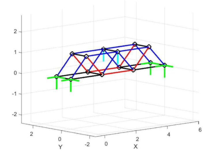
The dark blue elements of the truss were elements that underwent compression and the red elements were in tension. The green lines represent the reaction forces at the support locations on the truss and finally the cyan lines are where the load was applied. Below is the Matlab output of reaction forces at each of the support nodes and their magnitudes.

Results demonstrated that varying load and reaction force locations significantly affected internal forces, highlighting the importance of thoughtful truss design. Ultimately, the project showed that considering node and member locations could determine member tension or compression, and strategic load and reaction force placement could influence truss stability. The project provided valuable insights into truss design, loading, and construction considerations.
Shear Force and Bending Moment
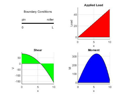
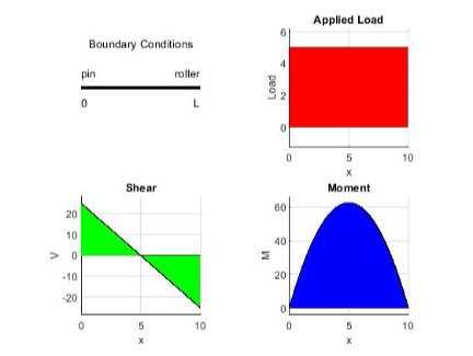
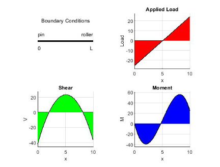
This statics project delves into the relationship between applied loads and shear force and bending moment in a beam, focusing on statically determinate beams with perpendicular distributed loads. The project is divided into two parts: understanding the provided shell code and modifying it to work with different support conditions. Initially, adjustments to variables like load (w), beam length (L), and number of intervals (N) are explored. Then, the task involves extending the code to accommodate two additional support conditions beyond the initial simply supported beam. Once the code runs successfully, experimentation with various load functions and support conditions was performed to understand their impact on shear force and bending moment.
Baseline Case
Constant Load Across Beam
Shifted Load
Point Load
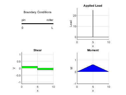
After implementing boundary conditions for both simply supported and cantilever beams, the program was verified through comparison with hand calculations, yielding consistent results. Subsequent tests examined various load scenarios, revealing significant differences in shear force and bending moment distribution. Test results indicated that altering the location and distribution of the applied load could lead to diverse beam responses. Notably, applying the load asymmetrically or as a point load generated distinct patterns in shear force and bending moment. These findings underscored the importance of considering load placement and distribution to mitigate excessive forces and moments along the beam.
Apoapsis Dwell Orbit
The project aims to design and analyze orbits for a spacecraft based on specific parameters such as orbital period, eccentricity, orbital inclination, and argument of periapsis. The primary objectives include understanding the structure and groundtrack of the orbit, as well as performing detailed analysis. A crucial concept in this project is "apoapsis dwell," which refers to the strategic positioning of the spacecraft's apoapsis (the point in its orbit farthest from the Earth) over a specific geographical region for a prolonged period. This concept plays a significant role in satellite deployment and operational planning. The project involves tasks related to orbit computation, visualization, and analysis to achieve its objectives effectively.
Task One
The first task involves designing orbits with specific parameters: a 24-hour orbital period, eccentricity of 0.25, orbital inclination of 63.4 degrees, and two values for the argument of periapsis (90 and 270 degrees). Using a Kepler solver, locations on the orbit are computed every five minutes for various values of the longitude of the ascending node (Ω) ranging from 0 to 180 degrees. Two plots are generated, one for each value of the argument of periapsis (ω), showcasing orbits in three-dimensional inertial space with Earth included. Observations are made regarding the orbit's structure as Ω varies, highlighting key differences between the two ω values.
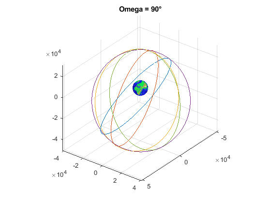
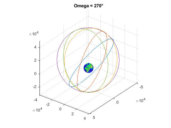
The plots of the orbits at both of the different arguments of periapsis appear to be the same. The orbits are visually identical using this as a basis for comparison. The only difference between the two images is the Earth's location. The structure as a function of the longitude of ascending node causes a shift in the direction of the orbit, but not in the orbit's shape.
Task Two
The second task involves analyzing the groundtrack of the orbit in relation to the longitude of the ascending node and argument of periapsis. Using computed Earth-relative longitude and geocentric latitude, two figures are generated for each value of ω (90 and 270 degrees), visualizing the groundtrack on a mercator projection. MATLAB code provided facilitates this display, with different markers denoting each of the five values of Ω. Observations on the groundtrack reveal interesting features, notably the orbit's coverage across Earth's surface. The key difference between orbits with ω = 90 degrees and ω = 270 degrees lies in the orientation and distribution of groundtrack coverage relative to Earth's surface, likely influenced by the argument of periapsis.
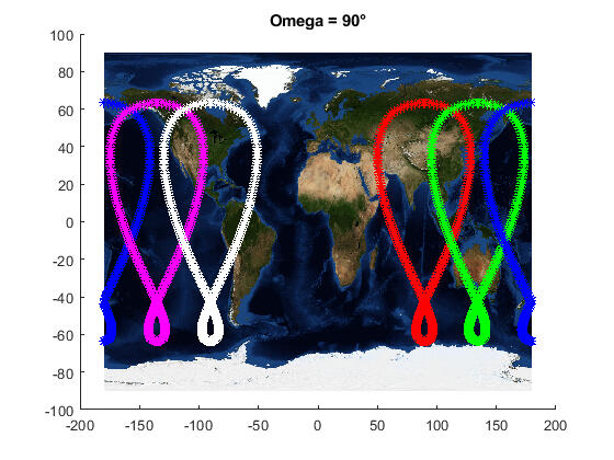
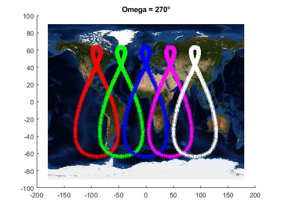
The groundtracks all follow the same shape, but at different locations, when the argument of periapsis is not changed. When changing the argument of periapsis, the orbits appear to flip about the equator and translate along it. Each orbit is vertically symmetrical, and feature a point where it overlaps itself.
Design and Manufacturing Lab
Group Report with: Donald Luchetti, Bhagirath Patel,
Dean Quilon, Robert Swiney, & Samuel Theis
The following project was a semester-long endeavor that involved designing and prototyping a mechanical manipulation device to interact with 3" wooden cubes and construct pyramids in a designated arena. The task included picking up and transporting the cubes to construct the pyramid within a 5-minute time limit, with the possibility of a time bonus if certain conditions were met. Design constraints included using permanent solutions for components, meeting specified manufacturing processes, and fitting within size and budget limitations. Teams were provided with a standard mobile platform and allocated a budget for additional materials. The project culminated in a competition where teams competed to build the highest-scoring pyramid within the time limit. The competition emphasized strategic design, collaboration, and adherence to project constraints and rules.
Each group had all of its individual members create preliminary designs via rough sketches, which were then made into physical models. Most models were cardboard, but I had a Lego Mindstorms set laying around in my closet that was perfectly suited to test out my ideas. Some ideas involved throwing the blocks across the arena, which would avoid having to drive back and forth to pick up the blocks, however my group decided to take my idea and modify it slightly for use in the final design.
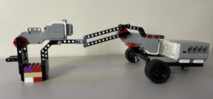
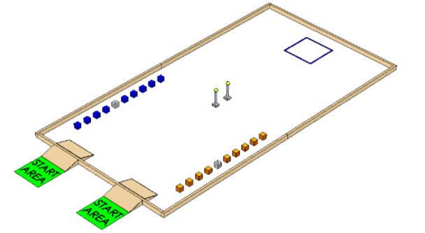
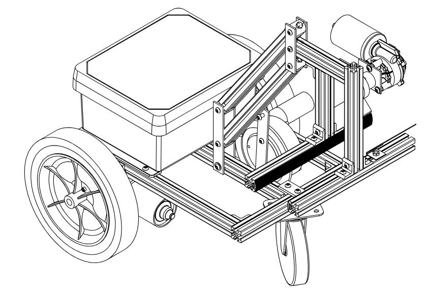
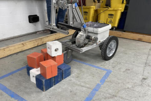
Initially, I designed the simple claw mechanism (as depicted above), which remained integral to our final product, as evident below. However, by widening the claw, our robot gained the ability to grip four blocks simultaneously. As illustrated in the arena diagram, the blocks were initially spaced apart. Leveraging our robot's bulldozer-like functionality, it efficiently nudged the blocks together, facilitating the seamless retrieval of three or four blocks in one go, which proved to be far faster than most other groups' methods.
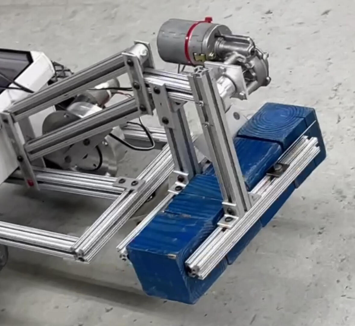
Below are the results from our competition trial. We managed to successfully construct the pyramid as mandated by the guidelines. However, our approach to retrieving the tennis ball proved ineffective, leading to the ball rolling onto the ground. This unfortunate occurrence prevented us from securing the bonus points associated with completing the pyramid with the tennis ball atop.
The project involved the utilization of a lathe, mill, and welding techniques to construct the robotic assembly, alongside learning Geometric Dimensioning and Tolerancing (GDT) principles and proper fastening techniques. Working within a team setting was invaluable throughout this project, as it allowed for collaboration, brainstorming, and division of tasks. Through teamwork, we leveraged diverse skill sets and perspectives, enhancing problem-solving capabilities and fostering creativity in design solutions. Additionally, collaborating with team members provided opportunities for knowledge sharing, skill development, and peer learning, further enriching the overall project experience. This collaborative environment not only facilitated the successful completion of the project but also cultivated essential interpersonal and communication skills necessary for professional engineering practice.
Structural Analysis and Optimization of a 2D Truss
This project involves the analysis and optimization of a 2D truss structure subjected to specific loading and boundary conditions. The initial task is to determine the stress distribution (σxx) and node displacements (u and v) using finite element analysis software (Abaqus). Upon completing the stress and displacement analysis, the project transitions to optimizing the truss design using the fully stressed design approach. The goal is to minimize material usage while ensuring that stress levels remain within allowable limits and adhere to minimum cross-sectional area constraints. Through iterative cycles, the project aims to find the optimum design configuration that balances structural integrity with material efficiency.
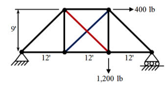
Truss Before Deformation
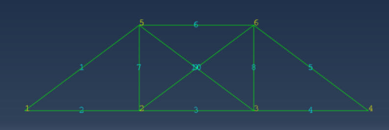
Truss After Deformation

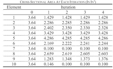
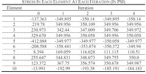
The analysis and optimization of the 2D truss structure yielded insightful results. The preliminary analysis showcased significant deformations, with node three experiencing the most substantial displacement. Stress analysis identified element five as the most stressed due to an applied force. The fully stressed design optimization process involved four iterations to meet allowable stress limits while adhering to minimum gage area constraints. While eight elements had stress values within 0.2 psi of the allowable limit, two elements required their areas to be set at 0.1 in² due to constraints. This project demonstrated the efficacy of the fully stressed design approach in optimizing truss structures, providing valuable insights into stress distribution and displacement. These findings contribute to the development of efficient and cost-effective structural configurations, applicable to real-world engineering challenges.
Integrated Analysis and Optimization of Torque-Arm Design
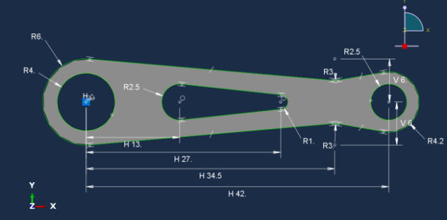
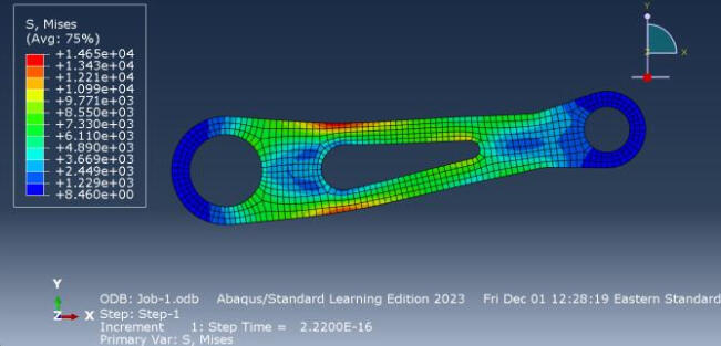
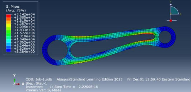
This project delves into the comprehensive analysis and optimization of a torque-arm model subjected to horizontal and vertical loads. Beginning with a preliminary analysis utilizing Mechanics of Materials principles, the project estimates vertical displacement and identifies the location and magnitude of maximum von Mises stress. Subsequently, employing Abaqus software, a constrained geometry model is constructed, allowing for the exploration of design variations. Convergence and element comparison studies are conducted to ensure accurate finite element solutions and assess the performance of different element types. The optimization phase involves minimizing mass while maintaining stress levels below allowable limits through strategic adjustments to three design variables. Through a systematic approach, the project aims to achieve an efficient and structurally sound torque-arm design while adhering to specified constraints and performance criteria.
Iteration 0
Iteration 1
Iteration 2
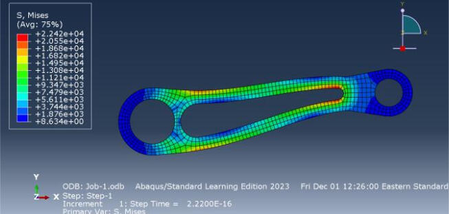

The analysis and design exploration of the torque-arm model underwent a systematic approach, encompassing tasks from preliminary analysis to final design optimization. Through Mechanics of Materials principles and computational tools like Abaqus, stress estimations, displacement calculations, and element comparisons were conducted. Key findings indicated the effectiveness of a 6-node triangular element in accurately predicting displacements and stress concentrations. Design optimization techniques successfully minimized mass while ensuring stress remained within safety limits. This study underscores the potency of mathematical modeling and computational simulations in refining engineering designs, offering valuable insights for real-world applications.
Impact Testing
During my initial semester with Gatorloop, our focus revolved around testing the vertical suspension system for the inaugural hyperloop pod iteration. To facilitate this, we engineered a fixture to securely hold the shock absorber in position, while I personally conceived and fabricated the distinctive blue 'target' affixed atop the shock. Subsequently, we subjected the suspension's shock absorber to a rigorous 40-pound mallet impact, meticulously recording displacement measurements throughout the event using an accelerometer. Leveraging this data, we successfully derived both the spring constant and damping ratio of the shock absorber, a pivotal step in our testing and refinement process.
Vertical Suspension System
As a member of the stability sub-team at Gatorloop, our mission was to engineer an innovative vertical suspension system for the next-generation hyperloop pod design. Given the propulsion method of the upcoming pod using a linear induction motor, maintaining a steady vertical displacement from the hyperloop track was paramount. My proposed solution (shown below), presented to the sub-team, aimed to blend practicality, ease of implementation, and efficacy to guarantee consistent pod height throughout the journey.

Self-Driving Car
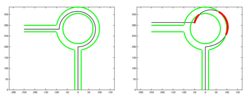
This project entailed designing an autopilot system for a Tesla Model S to navigate a round-about intersection autonomously. The project was divided into three phases, focusing on the vehicle's motion while considering spatial and temporal constraints to maintain lane integrity and traffic flow. The primary objective was to develop an autopilot specifically for Phase 2, where the vehicle had to execute a left turn with constant velocity and turn rate. Environmental constraints, such as round-about geometry and traffic dynamics, were factored in. The project involved defining dynamic variables, designing controllers for velocity and steering, and evaluating performance through unit-step responses. The autopilot had to meet performance criteria for steady-state error, response time, and overshoot. A sample code was provided to assist in the controller design process, emphasizing a systematic approach rather than trial-and-error tuning.Below is an example of a car with a fully functional autopilot system (left) that successfully navigated the roundabout and a car that was not able to navigate the roundabout correctly (right).
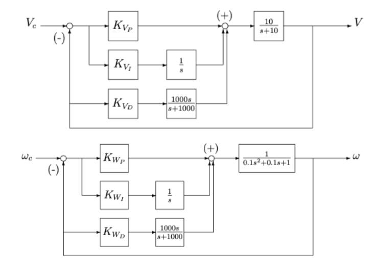
To construct the block diagrams below for each controller, I first analyzed the system dynamics and spatial constraints. Then, I represented the autopilot system as a combination of plant models and control gains. For the velocity controller, I depicted the dynamics of the vehicle's speed response to commanded inputs, incorporating the proportional, integral, and derivative control components.Similarly, for the steering controller, I illustrated the relationship between the commanded turn rate and the vehicle's steering dynamics. By manipulating the block diagrams and considering the system's response to input commands, I derived the equations that governed the control gains for both controllers, ensuring stability and optimal performance.
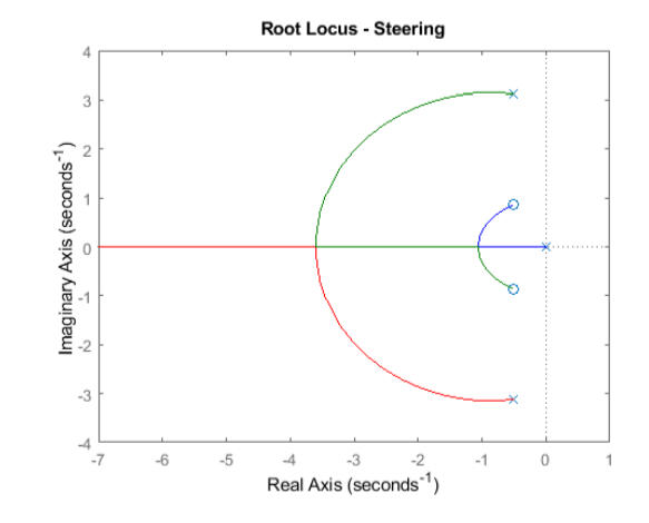
To create the root locus plots for each controller, I plotted the desired poles based on the system's stability requirements and performance objectives. Then, I manipulated the block diagrams of the velocity and steering controllers to formulate the characteristic equations governing their behavior. By varying the proportional, integral, and derivative control gains, I generated a range of root locus plots to visualize how the system's poles shifted in response to changes in the controller parameters. Through iterative analysis and adjustment of the controller gains, I identified the values that produced root locus plots with poles closely matching the desired locations, ensuring stability and desired performance characteristics for the autopilot system.

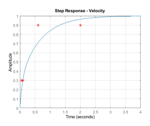
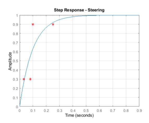
To create the step response plots for each controller, I first determined the control gains that produced desired pole locations using the root locus plots. Then, I used MATLAB to simulate the closed-loop system's response to a unit step input for both velocity and steering. By inputting the calculated control gains into the system model, I generated step response plots that depicted the vehicle's behavior in response to changes in velocity and steering commands. Through iterative tuning of the control gains, I adjusted the system's response to meet specific performance criteria, such as settling time, overshoot, and steady-state error. The resulting step response plots provided valuable insights into the effectiveness of the autopilot controllers and helped validate their performance against design requirements.
Final Result
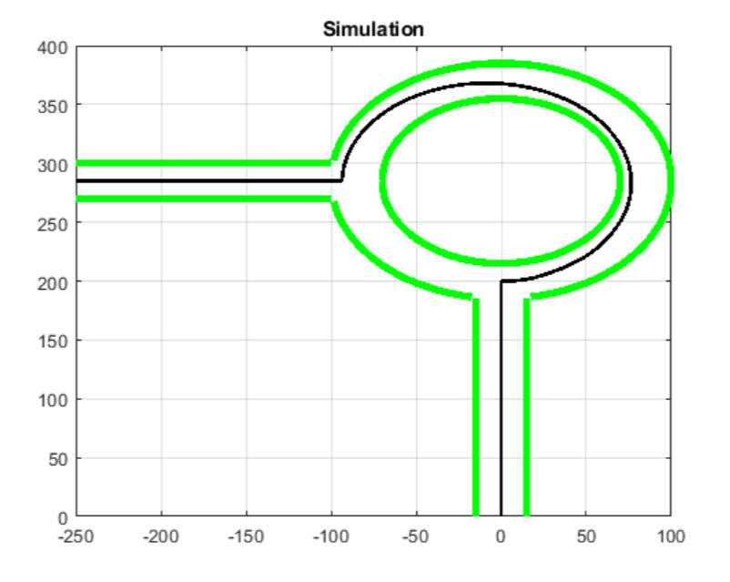
The selection of controller parameters involved determining the desired poles based on system dynamics and spatial constraints. Through iterative analysis, proportional, integral, and derivative gains were determined for both velocity and steering controllers to meet stability and performance criteria. The step-response plots verified that the controllers met the desired conditions without overshoot. The simulation results demonstrated that the vehicle remained within the roundabout bounds, confirming the effectiveness of the designed controllers in achieving the desired maneuver.
Accounting Optimization through Excel and VBA Integration
When I started at the Hilton Garden Inn, I received training on the data entry involved in the nightly accounting routine for the hotel. This process was quite tedious, requiring the handling of several reports, some of which were as long as eleven pages. Additionally, one had to perform calculations such as addition and subtraction before inputting the data into the accounting software, making it inefficient and error-prone.To address this issue, I took the initiative to streamline the process using Excel. Leveraging my previous experience with the software, I developed a workbook where users could paste the four reports into separate sheets, with the fifth sheet automatically generating totals. While this solution initially worked well, the inconsistency in report lengths posed a challenge. As the reports varied in length each week, cell positions changed, necessitating manual search and update tasks, making the process almost as tedious as manual calculations.Upon joining Homewood Suites, I discovered Excel VBA in the length of stay report and promptly integrated it into my accounting spreadsheet at the Garden Inn. With VBA, I implemented search algorithms that identified the correct category names and compiled the data into a separate sheet, presenting it neatly for input into the accounting software.The implementation of this code drastically reduced the accounting data entry time from 45-60 minutes to just 5 minutes.
Length of Stay Report
At the Homewood Suites, since it is a long-term stay hotel, the statistics and data about guest length of stay is analyzed at the corporate level. As a result, it is important for the night auditor to accurately report the length of stay in the nightly accounting report.The software utilized by the hotel can generate a report that lists each guest's room type, length of stay, and room rate. However, this report does not provide total amounts for how many guests are staying in each room type and for how long, and to determine this, one would have to manually comb through the report to find the number of guests staying in each room type, and then manually sort them by how long they are staying for. Needless to say, this would be a tedious and painstaking process.Below is a sample of this 'rate report' which provides the room type, length of stay, and room rates for every guest on a given night.
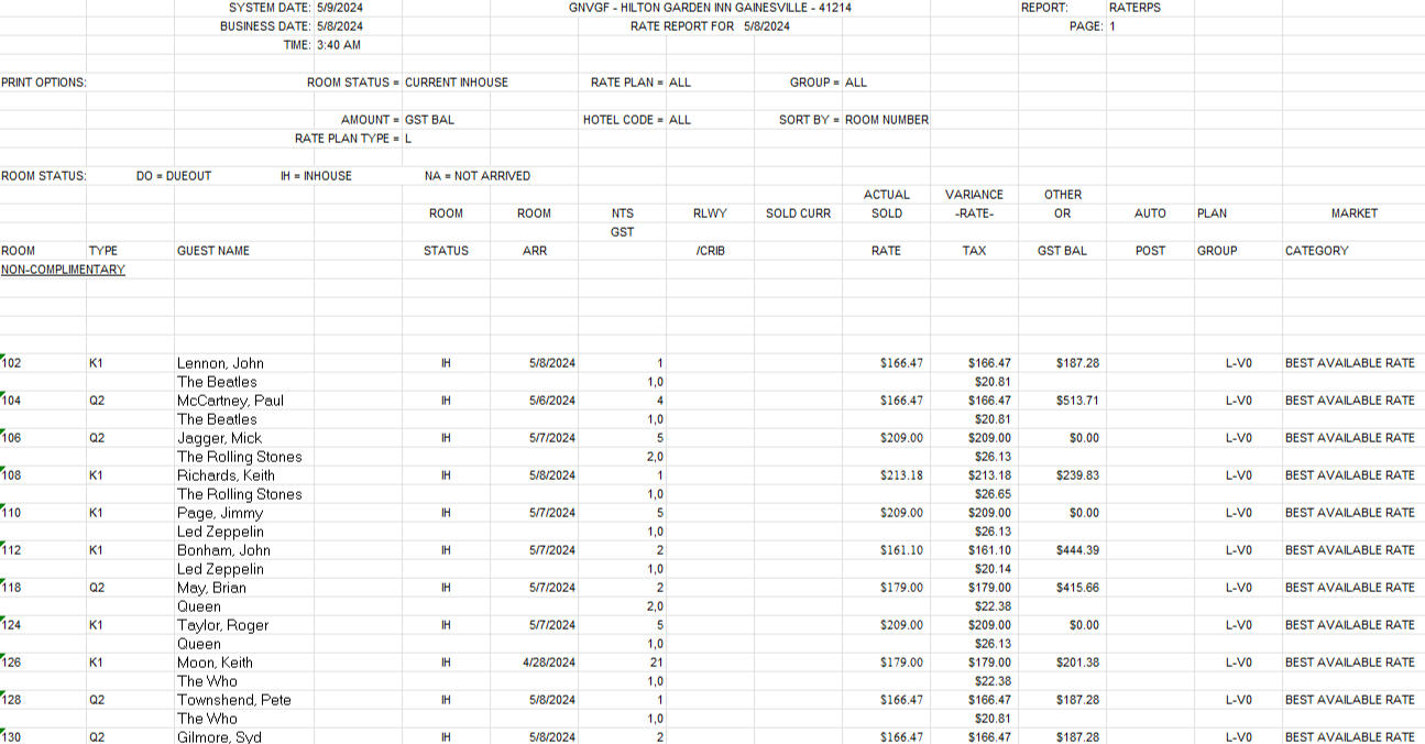
Note: guest names used in the sample report above are famous musicians and not actual guests of the hotel
The number of guests and total revenue of those guests in each of the 15 categories below needs to be found, which is a lengthy process to do manually.
| Room Type | Length of Stay |
|---|---|
| Queen Studio | 1-4 Nights |
| Queen Studio | 5-6 Nights |
| Queen Studio | 7-13 Nights |
| Queen Studio | 14-29 Nights |
| Queen Studio | 30+ Nights |
| One Bedroom | 1-4 Nights |
| One Bedroom | 5-6 Nights |
| One Bedroom | 7-13 Nights |
| One Bedroom | 14-29 Nights |
| One Bedroom | 30+ Nights |
| Two Bedroom | 1-4 Nights |
| Two Bedroom | 5-6 Nights |
| Two Bedroom | 7-13 Nights |
| Two Bedroom | 14-29 Nights |
| Two Bedroom | 30+ Nights |
To solve this, an Excel VBA code is used which takes the rate report, removes unnecessary information, sorts the guests by room type and length of stay, and then sums the quantity of guest and revenue of each of the 15 categories in the table above which are reported in the nightly accounting report.The problem was that the hotel was transitioning to a new software. The previous software had been in place since 2002 and the person who made the VBA code was long gone from the hotel. The new software still produced the rate report, but it looked drastically different from the old one, as seen below.
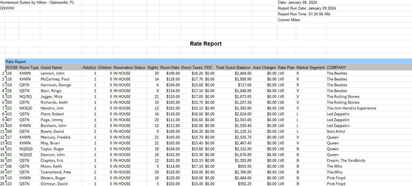
With the new software and the new rate report, the old VBA code no longer worked. So I took it upon myself to learn Excel VBA and was able to reprogram the code to work with the new rate report. I also added in a few fail-safes to make the code more intuitive and user-friendly for new employees.
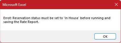
One mistake that I noticed would be very easy to make with the new software was not changing the date to the previous day's, which would return with the wrong guest manifest for the report. I was able to solve this by having the VBA code compare the date on the report to today's date and pop-up an error message (shown below) if the report date was not equal to yesterday's date.

Another mistake that would be easy to make was the user not changing the reservation status of the report to only show 'in house' guests. Checked out guests shouldn't be included in the report, so I added another few lines of code to ensure that all guests had the reservation status of "in house" before the code proceeded any further.
Catan Piece Holders & Shelf

Crafted with precision and passion, my custom Catan shelf stands as a testament to both functionality and creativity. Handcrafted from quality wood, this shelf elegantly holds 3D-printed Catan piece holders. The primary motivation behind creating these piece holders was to streamline the setup and cleanup process before and after games. My friends and I frequently played Catan during breaks between homework sessions, and having the pieces readily accessible significantly reduced the time required for storage in the provided plastic bags. What sets this piece apart are the thoughtful details: removable name plates adorning the front, adding a personal touch, and laser-engraved patterns on the back, infusing the shelf with a touch of artisanal charm. With its blend of craftsmanship and innovation, this Catan shelf is more than just storage—it's a work of art designed to elevate the gaming space.
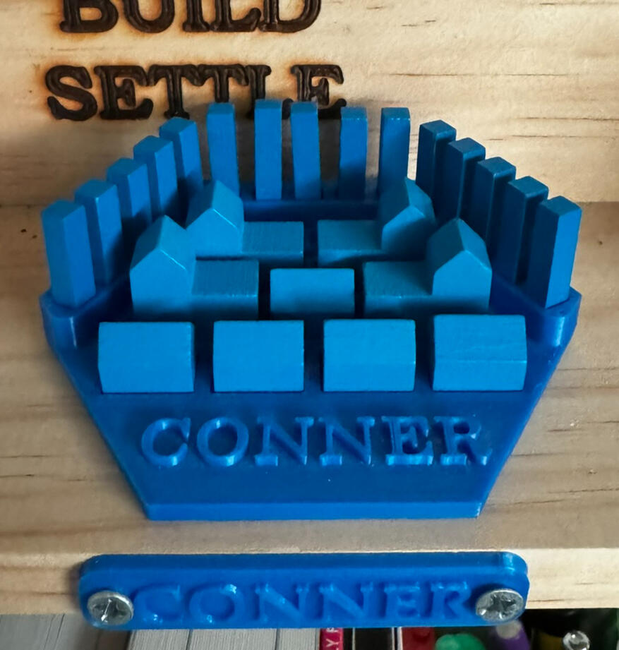
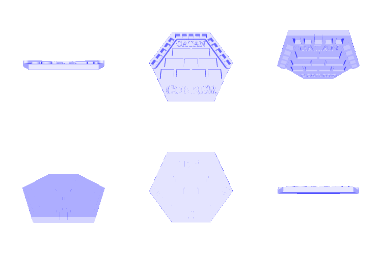
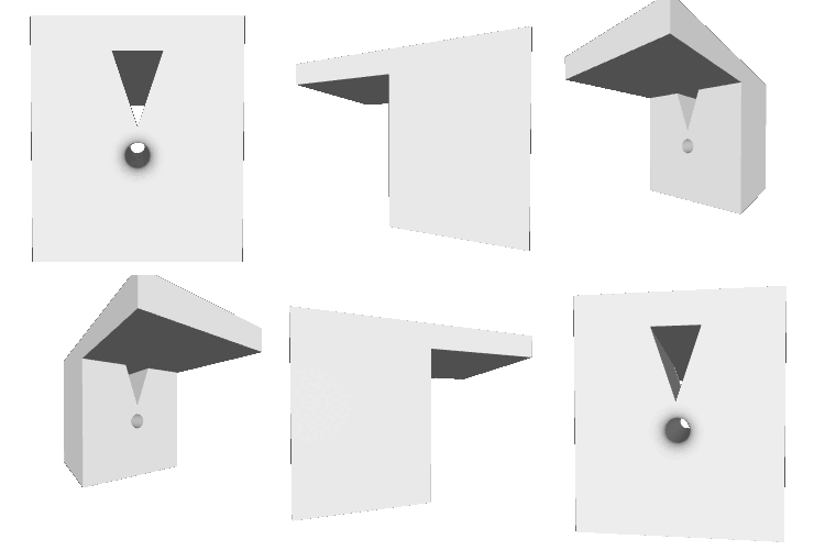
To align the name plates on the front, I crafted the small drill guide pictured below. This guide allowed me to line up the drill bit perfectly in the center of the wood for each of the pilot holes that I made before screwing in the name plates. I also left space on either side to expand the shelf and add extra players. Furthermore, the Catan board game and extension only includes pieces for six players, so to add a seventh set of pieces, I 3D printed the yellow set in its entirety.
At some point, I think I might redo the laser engraving on the back part of the shelf and may add wood stain to the entire shelf, in order to give it a nicer finish.
3D Printer Filament Holder/Shelf
When I first got my 3D printer, I quickly realized the hassle of constantly boxing and unboxing filament every time I wanted to change the color of my prints. To solve this, I devised a simple solution that could be mounted under a bookshelf above my printer. I bought a thin aluminum rod from Lowe's and 3D printed three mounts—one for the middle and one for each end—to secure it under the shelf. Then, I created a method to suspend the filament from the rod, allowing it to feed directly into the printer. This meant I didn't have to remove the filament from the mount attached to the printer; instead, I could feed filament as it hung from the shelf. The whole setup greatly reduced the time it took to switch out filaments.

Lego Rivendell & Piano Shelf
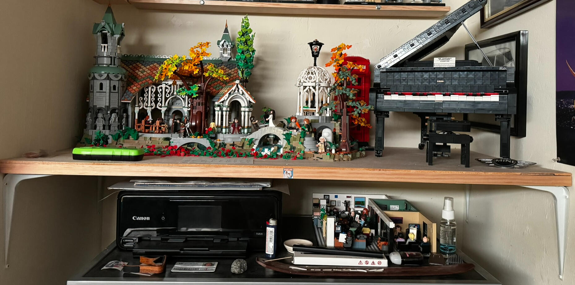
In an effort to optimize space and functionality within my apartment room, I embarked on a project to create a practical yet aesthetically pleasing shelf above the dresser alcove. To allow for use of my printer and showcase my Lego sets—the Lord of the Rings Rivendell and the piano—I used two sturdy 1x4 wooden pieces, placed to span the width of the alcove where my dresser sits. Over these supports, I affixed a thin plywood sheet to form the actual shelf, ensuring stability and durability. To reinforce the structure and prevent sagging under the weight of the Lego sets, I installed smaller 1x4 wood sections perpendicular to the main supports, providing additional support. This design not only accommodates the printer with ample clearance but also securely displays the heavy Lego sets, without compromising on aesthetics or functionality.
Vinyl Display
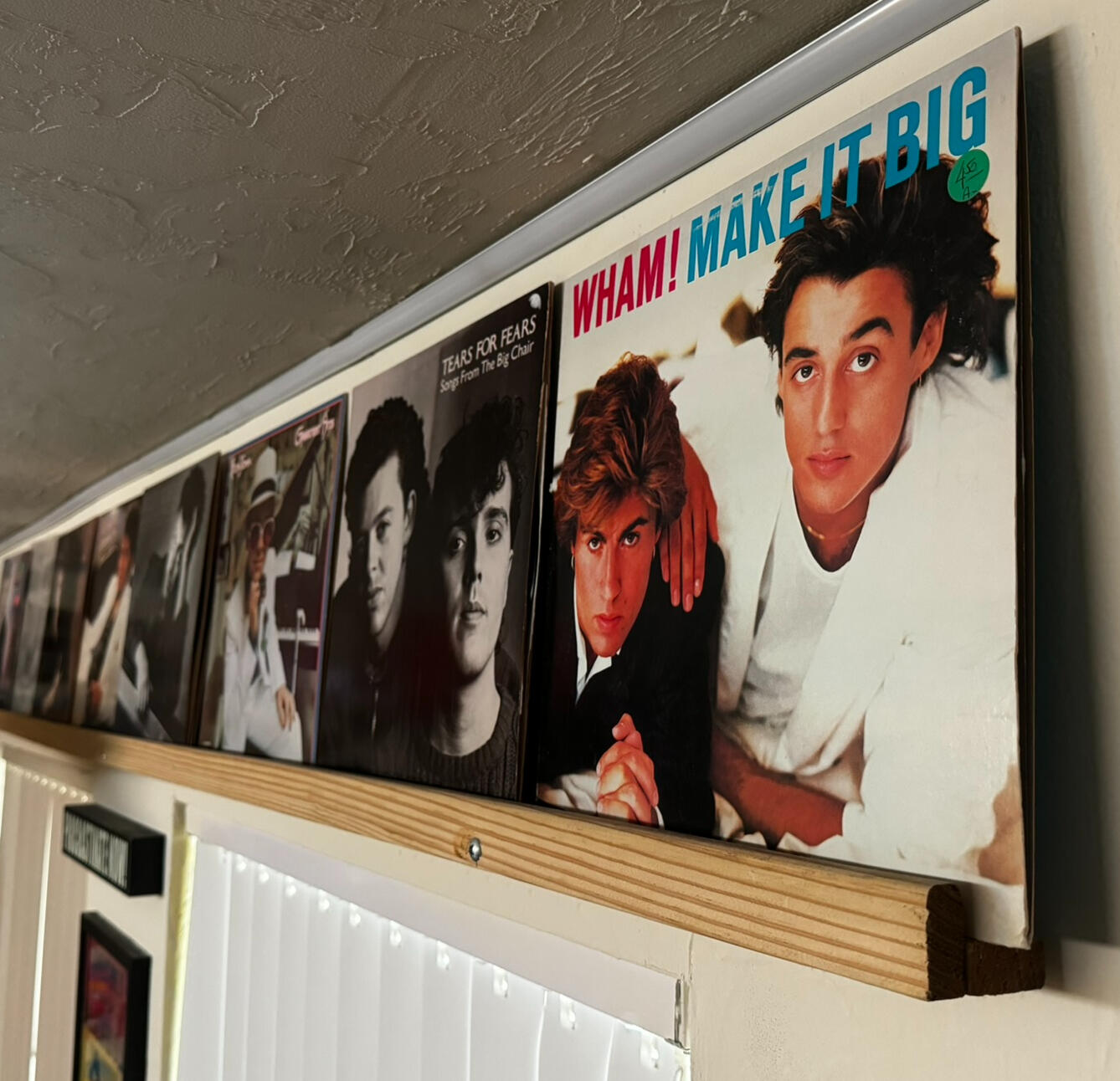
One of the first things I wanted when I moved into my apartment was a cost-effective way to display a handful of vinyl records. A friend of mine used sticky-tack to secure his records on the wall of his apartment. Not wanting to damage the sleeves, I did not want to use this method. Instead, I devised a simple method of displaying eight records, using two 0.5x1 pieces of wood and three bolts. I used the same drill guide as my catan shelf to align the pilot holes before screwing in the bolts. Wall anchors ensured that the wood was secured to the wall. The end result was a simple, cheap, and aesthetic method of displaying some of my records.
Train Shelf
During the summer of 2016, I embarked on one of my earliest significant projects: constructing a shelf capable of encircling my room with a model train. Positioned approximately a foot below the ceiling, the shelf accommodated two tracks that encircled the entire perimeter.Seeking to maximize the utility of the shelves, I aimed to incorporate a solution for hanging my extensive collection of hats from them. I opted to affix clothespins to the underside of the shelf using command strips. However, within days, the weight of the hats caused the command strips to fail, necessitating a new attachment method. After a number of ideas, I concluded that using wood glue to secure the clothespins would be the most effective approach. Yet, with the shelves already in place, this posed another challenge. Given the extensive nature of the task—hanging nearly 80 hats—I had to meticulously apply glue to each clothespin, ensuring it was precisely aligned 6 inches apart from the previous one, and then secure it in place with electrical tape to allow the glue to set.Upon completing the shelf, my 14-year-old self felt an immense sense of pride in the result. Not only could I now enjoy the spectacle of two trains circling my room's ceiling, but I also had a stylish way to showcase my hat collection.
When I moved out, I brought the shelves with me. Each of the four shelves, one on each wall, was dismantled and cut into four equal-length sections. In my new apartment, I mounted them as depicted below, and they have proven to be excellent for displaying my hats and storing various items.

Cantilever Train Shelf
I have a collection of model trains that I wanted to display to some degree in my apartment, but did not want to go to the full extent of the train shelf that I had in high school. Since the shelves only stick out 3.5" and the trains were so lightweight, I decided that I could use a similar method to display them as the vinyl shelf that I had built. For this, I used the same drill guide and was able to drill straight through the wood, allowing me to put bolts all the way through the wood and into the wall anchors. The end result was very minimalistic shelves that fit the trains perfectly.


I have used this concept to make shelves for some of my Lego sets, as seen below.


Fixing Broken Rally Light
On Christmas Eve of 2022, I stopped to get gas on my way home from a friend's house and while I was filling up, a truck backed into my car and drove off. Luckily, the only damage done was to the right rally light on the front of my car.
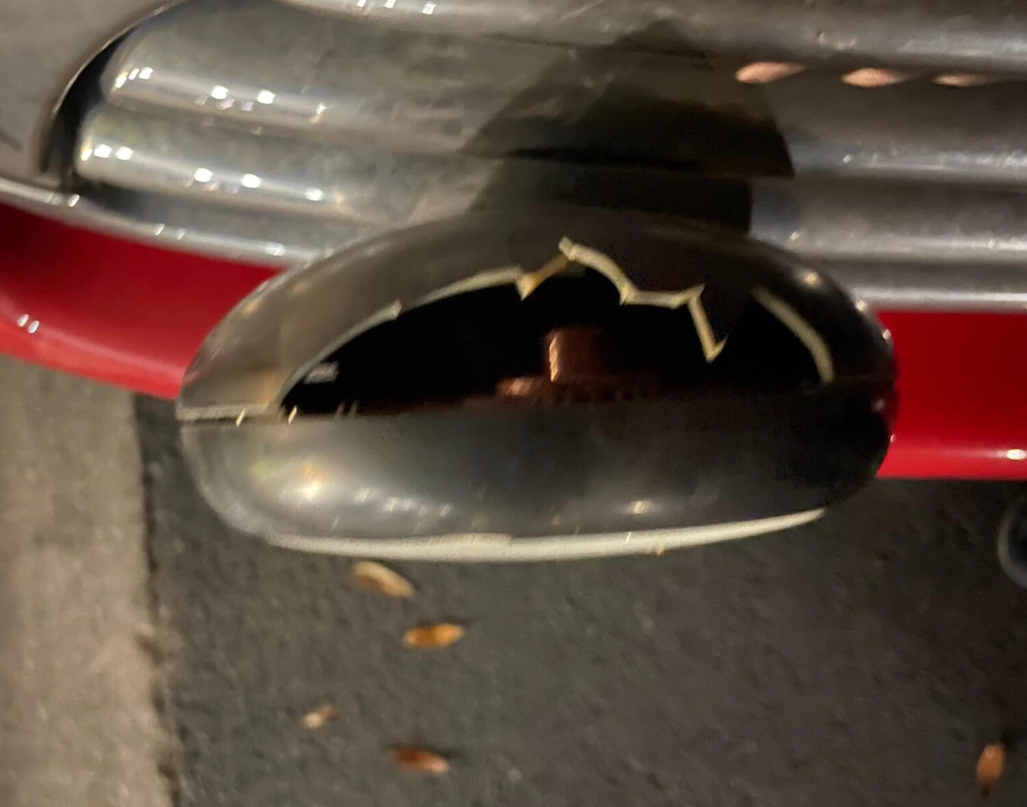
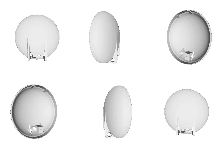
Rather than spending $100+ to purchase a replacement from MINI for the broken piece of plastic, I figured I could just replace it with my 3D printer. So I took the left rally light and disassembled it to get the plastic backpiece. From there, I took careful measurements and was able to model the piece in SolidWorks and print it out on my 3D printer. I used ABS, since it is very resistant to high heat and was able to install the part on the right rally light. The solution worked perfectly, and is still in place on my car, a year and a half later.

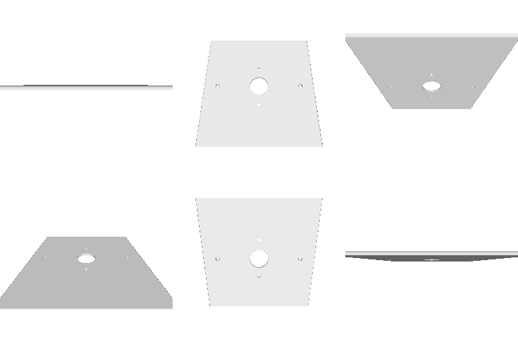
Thermostat Backplate
My mom received a smart thermostat as a gift and had me install it in our house. However, the previous thermostat was much larger than the new one and was not removed when the room was painted from white to green. To avoid having to go out and get a matching paint that might not align perfectly, I decided to create a backplate for the new thermostat that would cover up the part of the wall that had the old white paint on it. All in all, this was a very simple solution to the problem, and it works very well.
Miscellaneous 3D Prints
Polaroid Holder
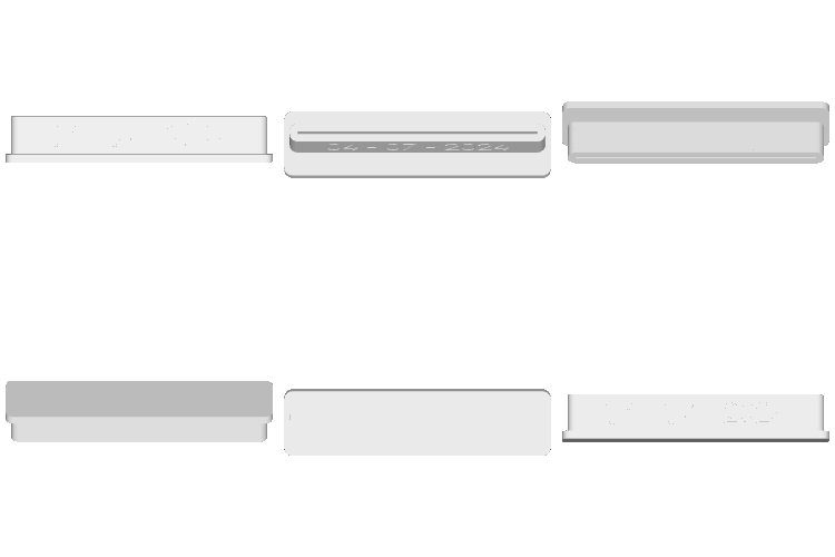
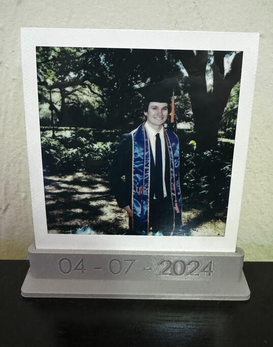
My friend Carissa is a professional photographer and shot my graduation photos for me when I graduated from UF. She has a tradition of taking a polaroid after every shoot, and I created this small display stand for the polaroid. On the front is the date of the shoot.
Lightsaber Holder
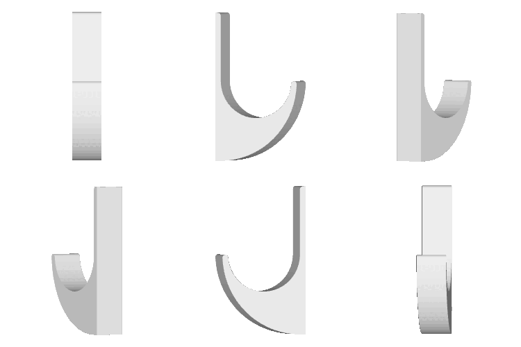
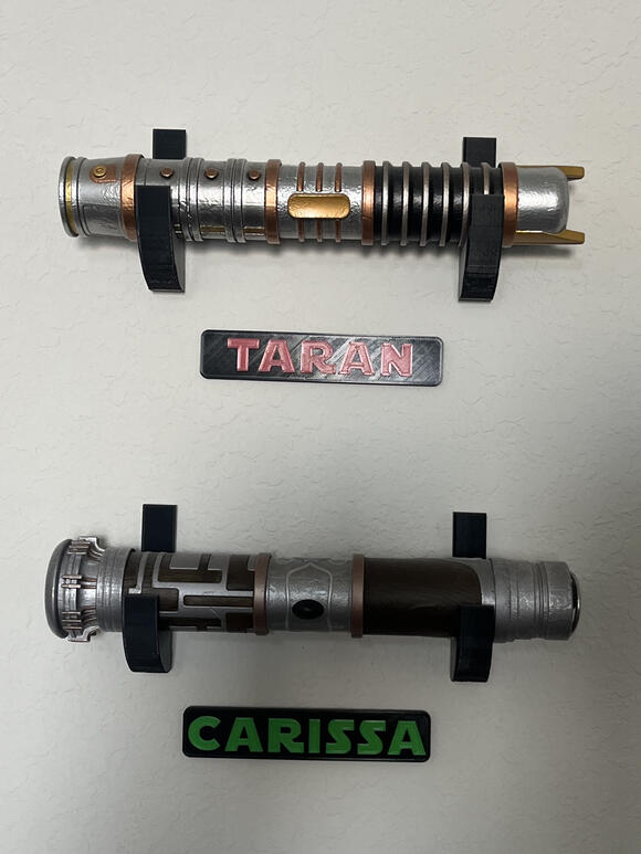
My friend Carissa is also a big Star Wars fan. She and her husband both have the lightsabers that you can buy from Galaxy's Edge at Disney's Hollywood Studios. As a gift to her, I created these mounts to hold the lightsabers, which were designed to be compatible with command strips. I also gave her name plates to put under each lightsaber, with the names being in the Star Wars font and in the color of each lightsaber.
Alexa Button Mount
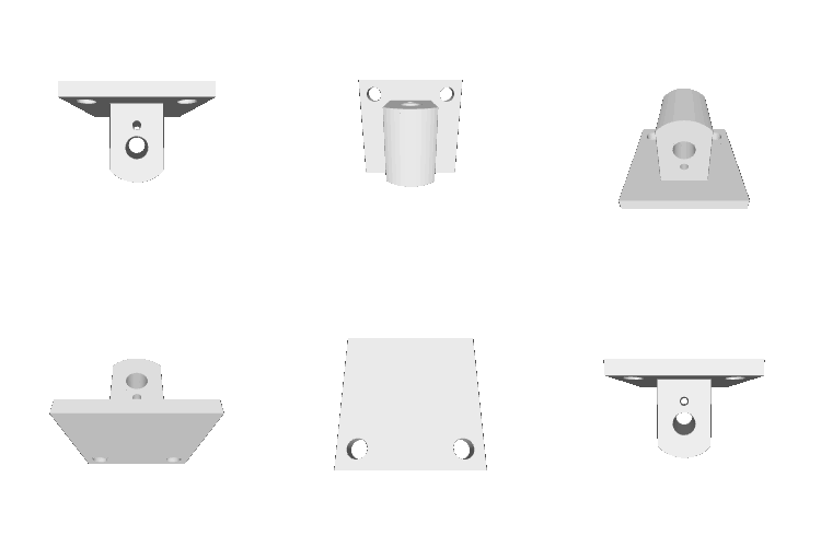
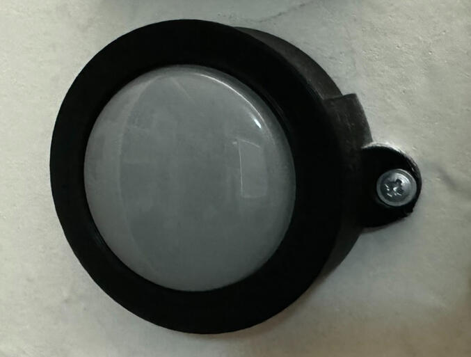
The lights in my room are controlled via my Amazon Echo. Since my apartment lease agreement prevents me from removing the light switch and replacing it with a smart switch, I used a 'Alexa Buttons' as a method of turning on and off the lights in my apartment and created this mount for them. I have one by the door and one by my bed, as a convenient way of turning on/off the lights without having to ask Alexa.
Laundry Door Wheel
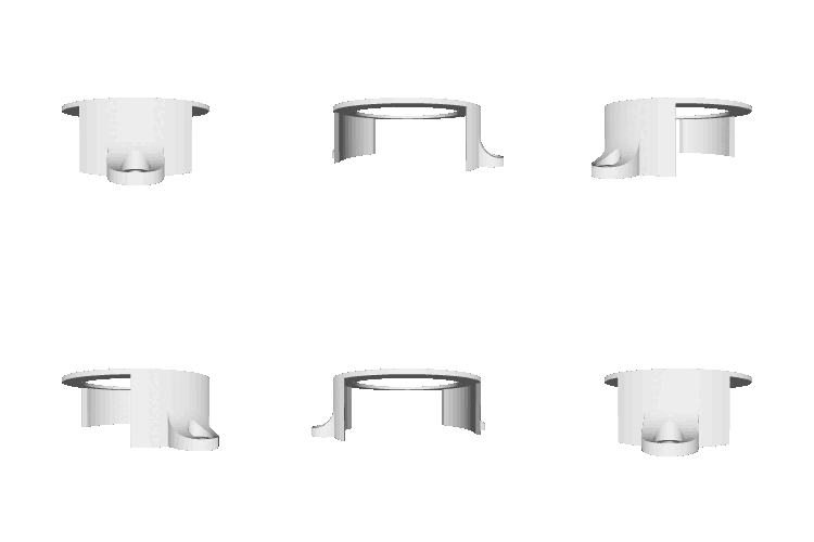
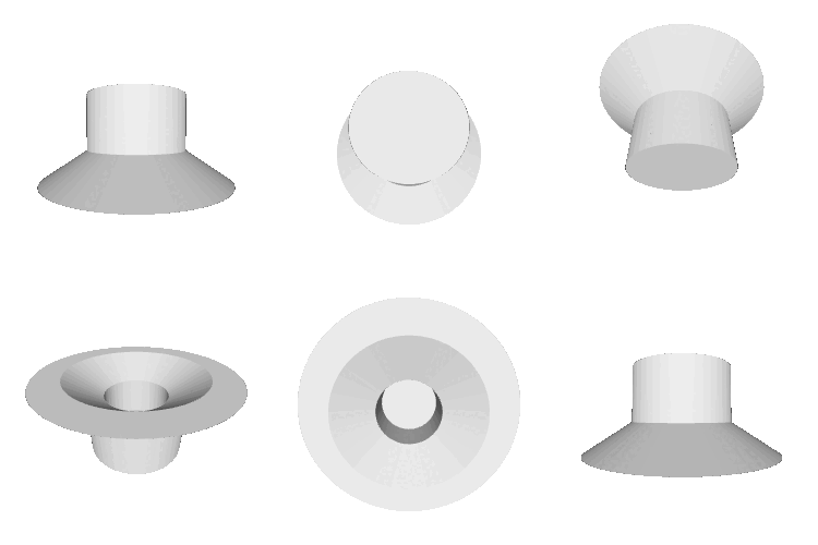
The sliding door to get to the washer and dryer in my apartment features a small guide at the top and bottom that fits snuggly in the track. When moving in to the apartment, one of the guides was missing, so I was able to render it and print it out. The door now opens and closes smoothly with the 3D printed guide.
Lego Guitar Mount
I wanted to display my Lego guitar somewhere, but was running out of shelf space. So I came up with this cantilever approach to mounting the guitar to the wall, using only two nails. It has held in place for over a year now, proving its sturdiness.

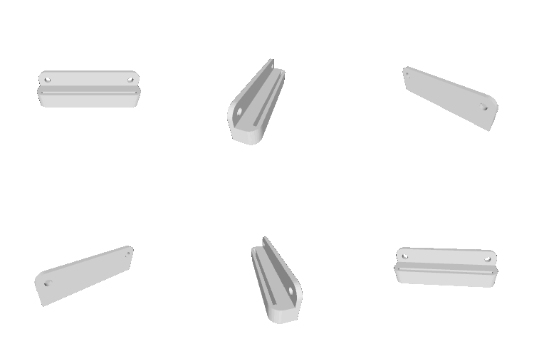
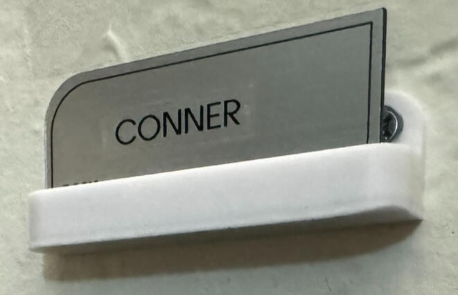
Name Tag Holder
When I started at the Hilton, I needed a place to put my nametag, such that I would not risk losing it. I created this simple mount for my nametag that I screwed into my wall, right above my car keys. It has made it very easy to remember anytime I am leaving for work.
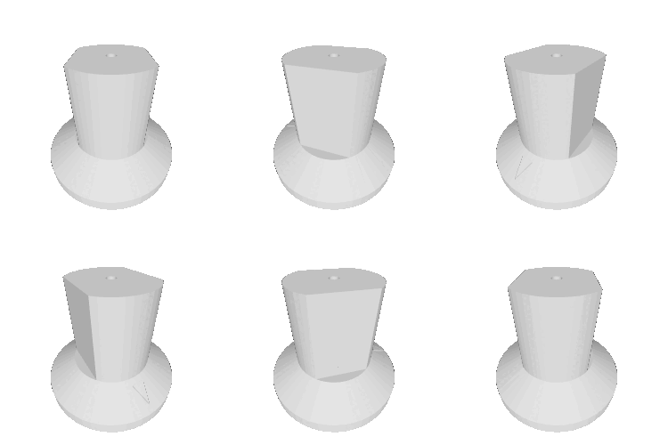
Guitar Amp Knob
My roommate purchased a used guitar amp off of Facebook Marketplace, and it was missing a knob. I was able to remove one of the other knobs and render it in SolidWorks and then print a replacement knob out for him. It even features the arrow indentation at the top of the knob.
Pez Holder
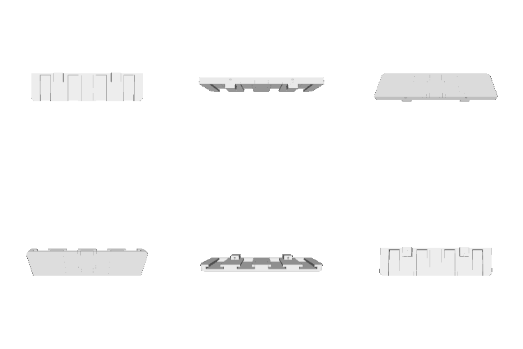
I wouldn't consider myself a collector of Pez dispensers, however I have been gifted many over the years. I came up with this little piece that secures into the wall with two nails and holds four Pez dispensers. I have printed two of them to display some of my favorite Pez dispensers.

Puck Light Mount
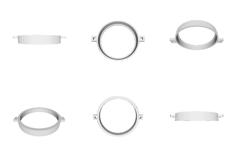
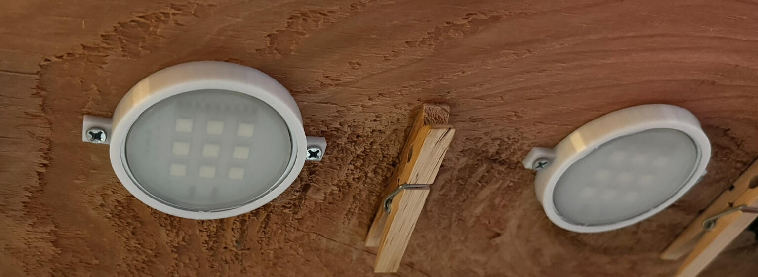
I purchased a set of four puck lights to put over my bed and serve as reading lights. The lights came with some velcro adhesive to secure the lights. I tried out the adhesive and it made the lights stick out from the shelf, and it looked tacky. To remedy this, I created these mounts to secure the lights in an aesthetic manner.
Speaker Spacer
I have a freestanding speaker in my room that is approximately three feet tall, which means it leans whenever it is bumped in to. Since I had the speaker placed directly in front of my wall, it would slam in to the wall, which was particularly annoying, not to mention a potential cause of damage to the wall. To fix this, I measured the distance between the wall and the speaker and created this little fix that secures to the wall with two nails and prevents the speaker from bumping into the wall.

Faucet Plug
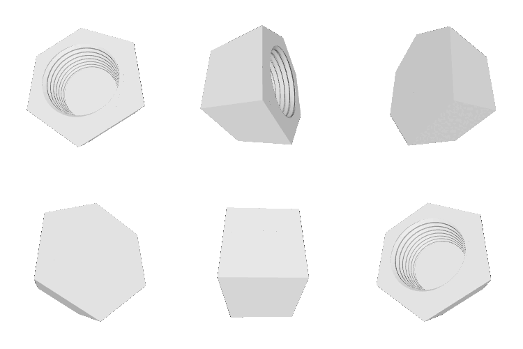
One night, I heard a dripping sound coming from my bathroom and determined the bathtub faucet was leaking (very slightly). It was a Friday night, so my apartment maintenance staff would not be able to fix it for at least another two days. Rather than waste water or money on a plug from Lowe's, I removed the faucet and measured the thread of the pipe sticking out. I then used SolidWorks to create this small plug, which served its purpose adequately for the next three days.
Monitor Mount
I created this small mount that is compatible with the Vesa mounts I have for my computer monitors, but this one can be screwed into the wall. To ensure it's strength, I printed this with 100% infill and the filament perpendicular to the load direction, to provide additional strength. The mount has functioned well for the past eight months.
